BNG: An Introduction

There are technologies and services that we use on a daily basis yet still we don’t know how they actually work under the hood.

One of these mysteries is the Broadband Networks, that we will try to demystify it in this article.

How are we connected to the Network ?

Boradband Network Sample

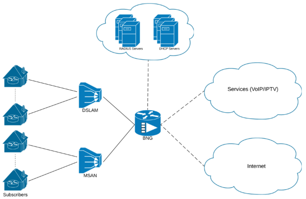
It starts with the CPE “Customer Premises Equipment” installed at your Premises.

The CPE is connected to the access network devices such as the DSLAM “Digital subscriber line access multiplexer” or MSAN “Multi-service access node” via various technologies for the Last Mile connectivity, some of these technologies are:

  • xDSL technologies like ADSL and VDSL.
  • xPON technologies like GPON and XGPON.

The access devices are then aggregated and backhauled to the site where the BNG “Broadband Network Gateway” resides, the BNG acts as the entry point for the customer towards the ISP “Internet Service Provider” network.

What is a BNG ?

BNG stands for “Broadband Network Gateway”, others might know it as BRAS which stands for “Broadband Remote Access Server“, both terms are often used interchangeably.

In short, a BNG is designed to provide and maintain a connection to a subscriber and provide him access into the Service Provider network to reach his contracted services such as Internet, VoIP and IPTV service.

BNG Functions

Traditionally a BNG has a router function and a subscriber/session management function.

The router function is concerned with routing traffic to and from the CPE through the broadband remote access aggregation devices such as DSLAM or MSAN and into the ISP networks.

The subscriber management can broken down into various functions including:

  • Subscriber access management, either PPPoE and IPoE.
  • AAA for subscriber Authentication, Authorization and Accounting.
  • IP Address Management, either from local or external pools.
  • RADIUS support to obtain user access policies from RADIUS servers.
  • Enforcing user policies such as QoS, ACL, Redirections, charging modes.[rml_read_more]

Session Establishment

When the CPE is configured and powered up, it attempts to establish a session with the BNG using either PPPoE or IPoE protocol.

The First Sign of Life is usually called on the first packet the CPE sends to the BNG to trigger the session establishment.

PPPoE Vs IPoE

Some consider the PPPoE a bit advantageous over IPoE since it natively has features like:

  1. Authentication, such as PAP and CHAP
  2. Keepalives
  3. Link aggregation via Multilink PPP

PPPoE Session Establishment

PPPoE has two phases, a discovery phase and a session phase.

The discovery phase objectives are a) exchanging the MAC address between the two ends and b) the CPE to select a BNG.

This is achieved through a series of PPPoE packets:

  1. PADI “PPPoE Active Discovery Initiation”: A broadcast packet sent by the CPE to discover available BNGs. This is considered the “First Sign of Life”.
  2. PADO “PPPoE Active Discovery Offer”: A unicast packet sent by the BNG containing its name in reply to the CPE PADI.
  3. PADR “PPPoE Active Discovery Request”: If more than one BNG replies with an offer “PADO”, the CPE selects only one BNG and sends a request to it confirming its acceptance to offer.
  4. PADS “PPPoE Active Discovery Session-Confirmation”: The BNG confirms the CPE requests and assigns a session-id.
  5. PADT “PPPoE Active Discovery Termination”: It can be sent by either the CPE and BNG to terminate the session.

The session phase is where the PPP session is established between the two end points, the session establishment has three phases:

  1. LCP “Link Control Protocol”: Negotiates various link layer properties like MRU “Maximum Receive Unit” and the authentication protocol to be used.
  2. Authentication: Authenticates the user using one of the available protocols like PAP and CHAP. In this phase the BNG can consult third-party like a RADIUS server for authentication.
  3. NCP “Network Control Protocol”: After successful authentication, IPCP “Internet Protocol Control Protocol” is used to negotiate and configure parameters like the IP Address and the DNS servers to be used by the CPE.

IPoE Session Establishment

The First Sign of Life of the IPoE session is the DHCP Discover packet sent by the CPE, once received by the BNG; it tries to authenticate the session.

Since IPoE sessions doesn’t have a built-in authentication method like PPPoE, the BNG could construct a username and a password to be used for authentication. The  BNG can consult a third-party like a RAIUS server for authentication in this phase.

After the successful authentication, the DHCP process continues. The BNG sends out the DHCP Offer, then the CPE responds with the DHCP Request, then finally the DHCP ACK by the BNG.

The BNG can be configured to act as either a DHCP Server or DHCP Proxy.

Also since IPoE doesnt have a keepalive or custom message types, the session can be terminated by either receiving a DHCP Release from the CPE or by reaching a timeout value for not having traffic either sent to or received from the CPE.

Session Accounting

Accounting is a crucial component in any Broadband network, as it is used in several areas like Billing, Quota Management, Resource Utilization and others.

It is the process of monitoring information related to a user session, such as user identity, start/stop times of network connection and number of packets and bytes consumed by the user.

After the successful establishment of the user session, the BNG can be configured to periodically send accounting information to a third-party RADIUS server.

Accounting messages have three types:

  1. Accounting Start: Sent directly after the session successfully established and brought UP, indicating the start of accounting for a specified session.
  2. Accounting Interim: An update that is sent periodically, the interval can be configured to a custom value.
  3. Accounting Stop: Sent after receiving the session termination request from the CPE, indicating the end of accounting for a specified session.
Lab Time

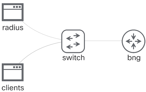
To illustrate the concepts explained above, we will go through a lab that covers some basic scenarios.

This lab uses an XRv9000 as a BNG and two Ubuntu machines, one acting as a RADIUS Server and the other simulating the PPPoE and IPoE Clients.

The scenarios are:

  1. PPPoE session
  2. IPoE session
  3. PPPoE session inside a VRF based on BNG selection
  4. PPPoE session inside a VRF based on RADIUS rule
BNG Lab Sample

BNG Configurations

AAA Configuration

First we will start by configuring the AAA.

The configuration tasks are:

  1. Define a RADIUS server
  2. Configure subscriber authentication, authorization and accounting to use the RADIUS server
!
radius-server host 10.0.0.2 auth-port 1812 acct-port 1813 key cisco
!
aaa accounting subscriber default group radius
aaa authorization subscriber default group radius
aaa authentication subscriber default group radius
!

PPPoE Common Configuration

There are some common PPPoE configurations that are shared among the different scenarios, those are:

  1. Createa PPPoE Profile, this is where you can configure some default values for PPPoE prameters like the MTU, per-card session limit , per-mac limit, etc …
  2. Create the first entry in the Dynamic-Template for session start event, in our case it will set the authentication to PAP and defines the accounting method.
  3. Create the first entry for the session start event in the Control Policy-Map that will handle the PPPoE sessions bring up.
  4. Configure the Access Interface by applying the PPPoE Profile and Control Policy-Map.
!
pppoe bba-group default
 service selection disable
!
dynamic-template
 type ppp PPPOE
  ppp authentication pap
  accounting aaa list default type session
!
policy-map type control subscriber PPPOE
 event session-start match-first
  class type control subscriber PPP do-until-failure
   10 activate dynamic-template PPPOE 
!
interface GigabitEthernet0/0/0/0.10
 service-policy type control subscriber PPPOE
 pppoe enable bba-group default
 encapsulation dot1q 10
!

Scenario#1

In this scenario we will configure a PPPoE session is in the Global Routing Table.

The configuration tasks are:

  1. Create an IP Address Pool for the sessions in the Global Routing Table
  2. Create a Loopback in the Global Routing Table to be used as an unnumbered interface under the Dynamic-Template.
  3. Create an entry in the Dynamic-Template that defines the IP Address pool to use and the unnumbered Loopback.
  4. Create an entry in the Control Policy-Map that will handle the session activation/authorization by sending the username and password sent by the CPE in the PPPoE packet.
!
pool vrf default ipv4 GLOBAL
 address-range 192.168.10.100 192.168.10.254
!
interface Loopback10
 description GLOBAL
 ipv4 address 192.168.10.1 255.255.255.0
!
dynamic-template
 type ppp GLOBAL
  ppp ipcp peer-address pool GLOBAL
  ipv4 unnumbered Loopback10
!
policy-map type control subscriber PPPOE
 event session-activate match-first
  class type control subscriber PPP do-until-failure
   10 activate dynamic-template GLOBAL
   20 authorize aaa list default identifier username password use-from-line
!

Scenario#2

In this scenario will configure an IPoE session in the Global Routing Table

We will use the IP Address pool and the Loopback interface from the previous scenario.

The configuration tasks are:

  1. Create a DHCP Server profile and attach it to the Access interface
  2. Create an entry in the Dynamic-Template that defines the unnumbered Loopback.
  3. Create a username attribute that will be used for authenticating the IPoE sessions, this is used since IPoE doesn’t have a built-in authentication method.
  4. Create a Control Policy-Map that will handle the session activation/authorization by sending the predefined username and password.
  5. Configure the Access interface with the IPoE session initiator and apply the Control Policy-Map under it.
!
dhcp ipv4
 profile IPOE server
  pool GLOBAL
  default-router 192.168.10.1
 !
 interface GigabitEthernet0/0/0/0.20 server profile IPOE
!
dynamic-template
 type ipsubscriber IPOE
  accounting aaa list default type session
  ipv4 unnumbered Loopback10
!
aaa attribute format IPOE_USER
 format-string "ipoe_user"
!
policy-map type control subscriber IPOE
 event session-start match-first
  class type control subscriber IPOE do-until-failure
   10 activate dynamic-template IPOE
   20 authorize aaa list default format IPOE_USER password cisco
!
interface GigabitEthernet0/0/0/0.20
 description ipoe
 ipv4 point-to-point
 ipv4 unnumbered Loopback10
 service-policy type control subscriber IPOE
 encapsulation dot1q 20
 ipsubscriber ipv4 l2-connected
  initiator dhcp
  initiator unclassified-source
 !

Scenario#3

In this scenario the BNG will have to take the decision to place the session inside the VPN_A VRF.

The BNG will make the decision based on a prefix in the username, the username in our scenario will be formatted as “name@vrf_name”.

The prefix in the username could also be called “Realm” or “Domain” in the RADIUS world.

In a real world scenario, there will always be an agreed upon format or structure the usernames assigned to Broadband subscribers.

The configuration tasks are:

  1. Create the VRF
  2. Create an IP Address Pool for the sessions inside the VRF
  3. Create a Loopback interface inside the VRf to be used an unnumbered interface under the Dynamic-Template
  4. Split the username and the prefix by creating two AAA attribute formats, one splits the username and the other splits the prefix
  5. Create an entry in the Dynamic-Template that defines the IP Address pool to use and the unnumbered Loopback.
  6. Create an entry in the Control Policy-Map above the previous entry that will handle the session activation/authorization by sending the username suffix and password sent by the CPE in the PPPoE packet.
!
vrf VPN_A
 address-family ipv4 unicast
  import route-target
   1:1
  export route-target
   1:1
!
router bgp 1
 vrf VPN_A
  rd 1:1
!
pool vrf VPN_A ipv4 VPN_A
 address-range 192.168.20.100 192.168.20.254
!
interface Loopback20
 description VPN_A
 vrf VPN_A
 ipv4 address 192.168.20.1 255.255.255.0
!
aaa attribute format VPN_A
 username-strip prefix-delimiter @
aaa attribute format USERNAME
 username-strip suffix-delimiter @
!
dynamic-template
 type ppp VPN_A
  ppp ipcp peer-address pool VPN_A
  vrf VPN_A
  ipv4 unnumbered Loopback20
!
policy-map type control subscriber PPPOE
 event session-activate match-first
  class type control subscriber VPN_A do-until-failure
   10 activate dynamic-template VPN_A
   20 authorize aaa list default format USERNAME password use-from-line
  ! 
  class type control subscriber PPP do-until-failure
   10 activate dynamic-template GLOBAL
   20 authorize aaa list default identifier username password use-from-line
!

Scenario#4

In this scenario we will configure a PPPoE session inside a second VRF named VPN_B, but this time the RADIUS will be the one to instruct the BNG using Vendor Specific AVPairs with the session parameters including:

  1. The VRF name
  2. The unnumbered Loopback
  3. The IP Address to pass along to the CPE in the IPCP phase.

So luckily this time we wont be configuring the BNG, instead we will be configuring the RADIUS Server with this user parameters.

! file path: /etc/freeradius/3.0/users 
!
user3   Cleartext-Password := "cisco"
        Service-Type = Framed-User,
        Framed-Protocol = PPP,
        Framed-IP-Address = 192.168.30.101,
        Framed-IP-Netmask = 255.255.255.255,
        Cisco-AVPair += "vrf-id=VPN_B",
        Cisco-AVPair += "ipv4-unnumbered=Loopback30"
!

ShowTime

Using Ubuntu package “pppoeconf” you can simulate multiple PPPoE users/clients.

The IPoE users can be simulated using the natively built-in DHCP Client “dhclient” tool.

Controlling the Client

On the client Ubuntu machine you can have multiple PPPoE users configured and a dedicated interface for the IPoE session.

To bring up the PPPoE sessions, use:

$ sudo pon user1
$ sudo pon user2
$ sudo pon user3

To bring down the PPPoE sessions, use:

$ sudo poff user1
$ sudo poff user2
$ sudo poff user3

To bring up the IPoE session, use:

$ sudo dhclient -v enp0s4

To bring down the IPoE session, use:

$ sudo dhclient -v -r enp0s4

HTH

recursive-lookup.com

Don’t miss our Articles & Podcasts!

We don’t spam! Read our privacy policy for more info.

Abdullah Medhat, CCIE#64416, is a co-founder at Recursive-Lookup, with over 10 years of experience in Service Provider networks. Always hungry for knowledge and learning  new technologies.

Leave a Reply